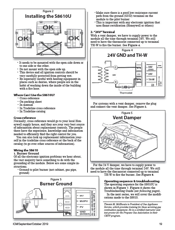
Figure 2
Installing the S8610U
• It needs to be mounted with the open side down or
to one side or the other.
• Do not mount with the open side up.
• This device and all ignition controls should be
very carefully protected from getting wet.
• Be especially careful with heating equipment in
places such as dairies, where people are in the
habit of washing down the inside of the building
with a fire hose.
Where Can I Use the S8610U?
• Cross-reference
• On packing sheet
• In manual
• In Tradeline cross-reference
• In Tradeline catalog
Cross-reference
Normally, cross-reference would go to your local Honeywell
supply house, and they are your very best source
of information about replacement controls. The people
there have the experience, knowledge and information
needed to efficiently find the right control for you.
You can also look up replacement information yourself
in the tradeline cross-reference at the back of the
catalog (to go over other sources of information).
Wiring the S8610
1. Burner Ground
Of all the electronic ignition problems we hear about,
the vast majority have something to do with the
grounding of the module. Below are some simple instructions.
• Ground to pilot burner (not cabinet, gas pipe,
ground)
• Make sure there is a good low resistance current
path from the ground (GND) terminal on the
module to the pilot burner
• This is important with any electronic ignition that
uses flame rectification (Honeywell or others)
2. “24V” Terminal
With a vent damper, we have to supply power to the
module all the time through terminal 24V. We still
need to have the thermostat connected up to terminal
TH-W to fire the burner. See Figure 4.
Figure 4
24V GND and TH-W
For systems with a vent damper, remove the plug
and connect the vent damper. See Figure 5.
Figure 5
Vent Damper
For the 24 V damper, we have to supply power to
the module all the time through terminal 24V. We still
need to have the thermostat connected up to terminal
TH-W to fire the burner. See Figure 6.
Operating sequence & troubleshooting
The operating sequence for the S8610U is
shown in Figure 7. Figure 8 shows the
Troubleshooting Guide (see following pages).
In the next series, we will cover the modifications
made to the S8610.
Timmie M. McElwain is President of Gas Appliance
Service, which provides training for those servicing gas
combustion equipment. He is a certified instructor and
test proctor for the Propane Gas Association in their
CETP program.
Figure 3
Burner Ground
ICM/September/October 2019 19