The various diagrams featured in this article
will show you the circuits involved...
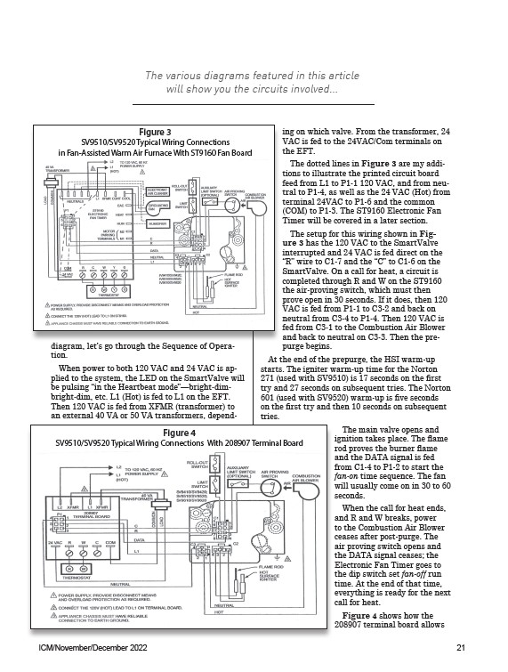
Figure 3
SV9510/SV9520 Typical Wiring Connections
in Fan-Assisted Warm Air Furnace With ST9160 Fan Board
diagram, let’s go through the Sequence of Operation.
When power to both 120 VAC and 24 VAC is applied
to the system, the LED on the SmartValve will
be pulsing “in the Heartbeat mode”—bright-dimbright
dim, etc. L1 (Hot) is fed to L1 on the EFT.
Then 120 VAC is fed from XFMR (transformer) to
an external 40 VA or 50 VA transformers, depending
on which valve. From the transformer, 24
VAC is fed to the 24VAC/Com terminals on
the EFT.
The dotted lines in Figure 3 are my additions
to illustrate the printed circuit board
feed from L1 to P1-1 120 VAC, and from neutral
to P1-4, as well as the 24 VAC (Hot) from
terminal 24VAC to P1-6 and the common
(COM) to P1-3. The ST9160 Electronic Fan
Timer will be covered in a later section.
The setup for this wiring shown in Figure
3 has the 120 VAC to the SmartValve
interrupted and 24 VAC is fed direct on the
“R” wire to C1-7 and the “C” to C1-6 on the
SmartValve. On a call for heat, a circuit is
completed through R and W on the ST9160
the air-proving switch, which must then
prove open in 30 seconds. If it does, then 120
VAC is fed from P1-1 to C3-2 and back on
neutral from C3-4 to P1-4. Then 120 VAC is
fed from C3-1 to the Combustion Air Blower
and back to neutral on C3-3. Then the prepurge
begins.
At the end of the prepurge, the HSI warm-up
starts. The igniter warm-up time for the Norton
271 (used with SV9510) is 17 seconds on the first
try and 27 seconds on subsequent tries. The Norton
601 (used with SV9520) warm-up is five seconds
on the first try and then 10 seconds on subsequent
tries.
The main valve opens and
ignition takes place. The flame
rod proves the burner flame
and the DATA signal is fed
from C1-4 to P1-2 to start the
fan-on time sequence. The fan
will usually come on in 30 to 60
seconds.
When the call for heat ends,
and R and W breaks, power
to the Combustion Air Blower
ceases after post-purge. The
air proving switch opens and
the DATA signal ceases; the
Electronic Fan Timer goes to
the dip switch set fan-off run
time. At the end of that time,
everything is ready for the next
call for heat.
Figure 4 shows how the
208907 terminal board allows
Figure 4
SV9510/SV9520 Typical Wiring Connections With 208907 Terminal Board
ICM/November/December 2022 21