Table 2: Model Number Suffix Letter Designation
Model No. Ambient Temperature Pressure Regulator
Suffix Letter Range Type
H 0°F to +175°F (-18°C to +79°C) Slow-opening
K -40°F to +175°F (-40°C to +79°C) –
M -40°F to +175°F (-40°C to +79°C) Standard
N 0°F to +175°F (-18°C to +79°C) Two-stage slow-
opening
P -40°F to +175°F (-40°C to +79°C) Step-opening
Q -40°F to +175°F (-40°C to +79°C) Two-stage standard
S (SV9510, -40°F to +175°F (-40°C to +79°C) Standard
SV9520 only)
Line voltage polarity sensing models monitor the
line voltage input connection to assure line voltage
polarity is correct. If line voltage polarity is incorrect,
the LED diagnosis code will flash and the control will
not respond to the call for heat. These models also
provide added LED diagnostic codes (“6+”) to indicate
the reason the control has moved to the lockout state.
Depending on models, various timings are available,
such as 15 or 30 seconds pre-purge; post-purge
five seconds (typical depending on model; this is
not available when the SmartValve™ is connected
directly to the thermostat); five, seven or nine seconds
trial for ignition; 60-minute soft lockout; three retries;
four trials before lockout. The other unusual feature
is that the draft inducer is now controlled from the
SmartValve™; depending on the version, this is accomplished
by either interrupting the 120 volts or
24-volt signal. This will be defined as each diagram is
discussed.
The capacities on SV9510, 20 and 40½" x ½"
200,000 BTUs maximum and on the SV9610, 20,
40¾" x ¾" is 415,000 BTUs.
Figure 1 is an illustration of the top view of the
valves. The C3 connector is for 120-volt power, and this
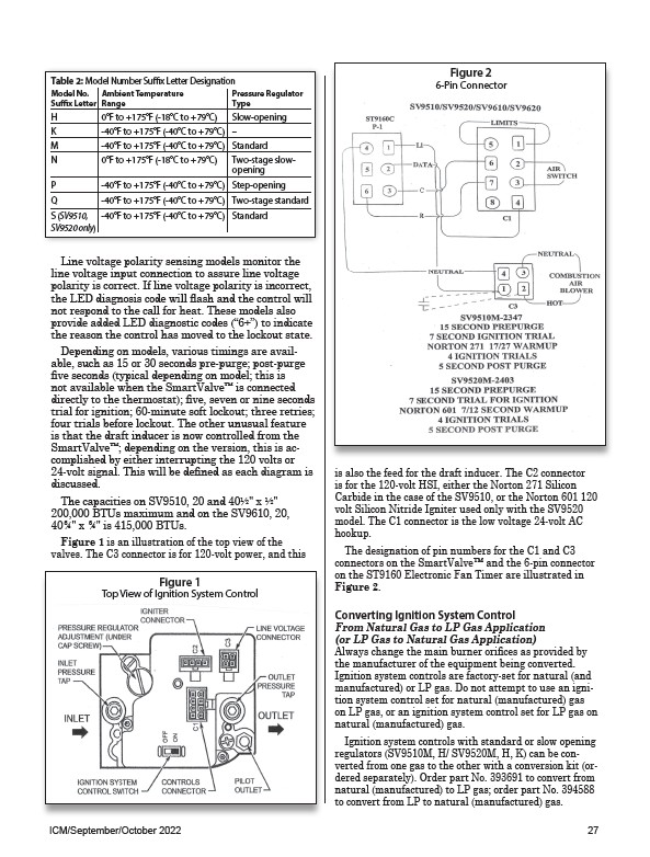
Figure 2
6-Pin Connector
is also the feed for the draft inducer. The C2 connector
is for the 120-volt HSI, either the Norton 271 Silicon
Carbide in the case of the SV9510, or the Norton 601 120
volt Silicon Nitride Igniter used only with the SV9520
model. The C1 connector is the low voltage 24-volt AC
hookup.
The designation of pin numbers for the C1 and C3
connectors on the SmartValve™ and the 6-pin connector
on the ST9160 Electronic Fan Timer are illustrated in
Figure 2.
Converting Ignition System Control
From Natural Gas to LP Gas Application
(or LP Gas to Natural Gas Application)
Always change the main burner orifices as provided by
the manufacturer of the equipment being converted.
Ignition system controls are factory-set for natural (and
manufactured) or LP gas. Do not attempt to use an ignition
system control set for natural (manufactured) gas
on LP gas, or an ignition system control set for LP gas on
natural (manufactured) gas.
Ignition system controls with standard or slow opening
regulators (SV9510M, H/ SV9520M, H, K) can be converted
from one gas to the other with a conversion kit (ordered
separately). Order part No. 393691 to convert from
natural (manufactured) to LP gas; order part No. 394588
to convert from LP to natural (manufactured) gas.
Figure 1
Top View of Ignition System Control
ICM/September/October 2022 27