Gas/Propane Basics
Hot Surface Ignition
Troubleshooting
Part Two
When checking the flame signal, it is important
to realize that when a hot surface igniter (HSI)
is also being used as a sensor, there will be
some difficulty in checking the micro-amps. There are
several procedures you can follow. In my opinion, the
procedure in Figure 1 is the preferred method. It is also
important to note the technical bulletin from Norton
(Coorstek) points out that the igniter can have a buildup
of oxide that can cause it to be a poor sensor.
It has been my observation that when the igniter is
used on atmospheric burners, exposing the igniter to
whatever contaminants are in the room, the igniter is a
poor sensor. Atmospheric burners tend to work a little
better when the igniter is used in a sealed combustion
chamber that gets its air for combustion from the
outdoors.
Direct Sense: The Igniter as a Flame Rod
Sensing through flame rectification, whether “direct”
(through the igniter) or “remote” (separate flame rod),
involves certain components and variables. The object is
to use the ionized particles in the flame (burning gas) to
conduct a current and complete an electrical circuit.
The control module initiates an AC signal that is sent
out to the igniter. The flame acts as a diode and converts
the AC signal to a rectified DC signal. The strength of
the signal required to prove flame, and therefore keep
the gas valve open, is dependent on the control module
and varies from one control manufacturer’s board to
another.
Signal strength can be affected by:
• the type of burner,
• the position of the igniter in the flame,
• the age of the igniter,
• the type of gas,
• coating on the igniter and
• any impurities that build up on the system over time.
It is imperative that the flame remains in contact with
the burner, and that the burner and control module have
the same common ground.
When using the igniter as the sense unit, it is important
to remember that as an igniter ages, a thin oxide
(Si02) layer is formed on the surface. This is part of the
normal aging process of a silicon carbide igniter. As this
oxide layer is formed, it actually helps seal the underlying
SiC grains and inhibits further rapid oxidation. The
silica (silicon oxide) that has formed is a glass, which is
an insulator and will diminish the strength of the flame
Timmie McElwain
President, Gas Appliance Service
timmcelwain@gastcri.com
signal that is being sent out. Whether the signal will still
be strong enough to keep the valve open as the igniter
ages is application-dependent.
Although direct sense can be a very feasible alternative,
in the final analysis, it is the responsibility of the
Original Equipment Manufacturer’s (OEM) testing to
determine if it is a viable solution for the particular application.
Checking microamps with systems using the igniter
as a sensor can sometimes be difficult. The problem is
distinguishing between the 120 volts AC (VAC) power to
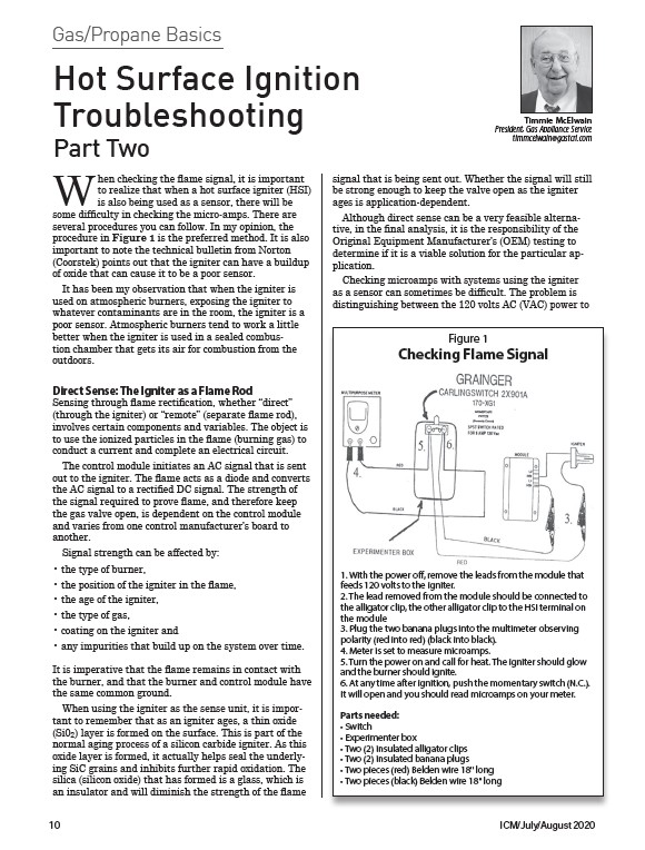
Figure 1
Checking Flame Signal
1. With the power off, remove the leads from the module that
feeds 120 volts to the igniter.
2. The lead removed from the module should be connected to
the alligator clip, the other alligator clip to the HSI terminal on
the module
3. Plug the two banana plugs into the multimeter observing
polarity (red into red) (black into black).
4. Meter is set to measure microamps.
5. Turn the power on and call for heat. The igniter should glow
and the burner should ignite.
6. At any time after ignition, push the momentary switch (N.C.).
It will open and you should read microamps on your meter.
Parts needed:
• Switch
• Experimenter box
• Two (2) insulated alligator clips
• Two (2) insulated banana plugs
• Two pieces (red) Belden wire 18" long
• Two pieces (black) Belden wire 18" long
10 ICM/July/August 2020